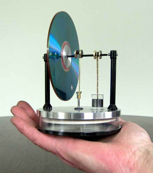
The objective of this little project
Earlier I made a LTD Stirling that needs a minimum temperature difference of 12°C between the lower and upper plate; see the concerning page.
I had the following intentions with making a second version of it:
1. Significant easier to make;
2. Decreasing the minimum required temperature difference with some degrees Celsius;
3. Transparent cylinders for displacer and working piston;
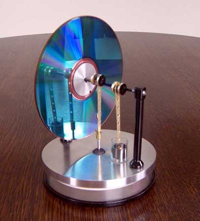
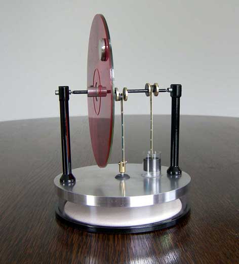
4. A more "eye catching" appearance.The work-out
``
1. Making the parts.a. The transparent cylinders.
For the transparent displacer cylinder I cut a slice out of a (Dutch) biscuit box with 100mm outer diameter and 2mm wall thickness and lathed the rims nicely flat.
The glass cylinder for the working piston is cut from a standard test tube.
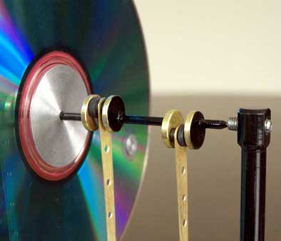
b. The fly wheel.
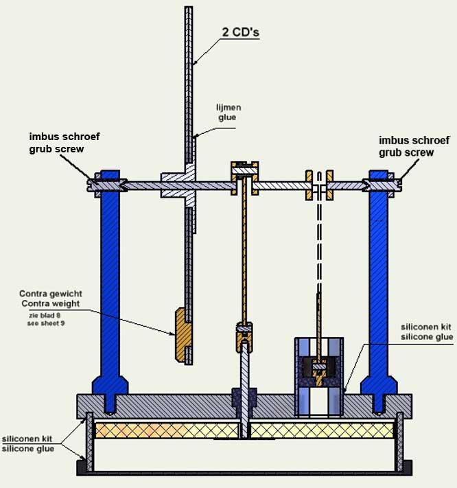
For this I used two CD's that I glued on an aluminium kernel. Much easier than making a metal fly wheel and good looking if one takes nice coloured or fancy decorated CD's.c. The displacer.
This time I used 5mm thick balsa wood as is used for model air planes; very light, stiff and flat. First glue the aluminium kernel in the somewhat oversized displacer. Screw the displacer axis in the kernel and put that in the clutch of the lathing machine. Grind the diameter carefully to a diameter that is 2mm smaller that the inner diameter of the transparent cylinder so there will be a clearance of 1mm between the displacer and the cylinder.
d. The aluminium cylinder plates.
Except for the outer rim in what the transparent cylinder will be glued (as the very last work step) the whole bottom plate is only 1mm thick for rapid warming-up. This is especially important when you want to let the engine run on your hand.
The upper plate is relatively thick to make the mounting of the parts on that possible but, for all, to make a substancial heat capacity. This contributes to keep the temperature as low as possible together with the fact that the plate is polished. With the absence of metal fixing spacers at the circumference the heat conduction from bottom plate to upper plate is almost zero. The upper plate will only be warmed-up slowly by the air in the system which is inevitable and part of the Stirling principle. It is my experience that the effect of cooling fins in the upper plate is hardly noticeable and even not at all present at start-up when the temperature of this plate is equal to the ambient temperature. So cooling fins won't help at starting-up the engine on your hand. Cooling the upper plate with a small ice cube in an aluminium box on the upper plate is very effective although it may be considered as a forced remedy. It is just the way you look at it.
e. The glide bearing for the displacer axis.
This is the most critical part of a low temperature Stirling. It must be leak free as possible with the lowest possible friction and this is also valid for the working piston in its cylinder. The best thing to do is to applying standard axis in a standard glide bush, for instance as used in all kinds of small devices as printers, hard disks, etc. I never succeed to make such a quality with self made bronze bushes. A good alternative is to make a graphite bush and that's what I did in this case. This graphite bush is glued in the upper plate.f. The crank shaft.
In fact this is the only part that requires some (soldering) skill but with some accuracy and patience it can be done very well. For making the parts and the assembly I best can refer to the sheets 3 and 7 of the drawing plan and the remark 4 on drawing sheet 8; see also point "d" on paragraph 2 below.g. The point bearings of the crank shaft.
In stead of ball bearings I here applied point bearings as used in clocks. I did this before successfully with my Egg Cup Stirling. Although I cannot measure it I have the strong feeling that the friction of this point bearing is even lower than that of a ball bearing, for sure when you make a fractional clearance there. Moreover it is a very simple construction with what the chamfered ends of the crank shaft are turning around in conical holes in M4 screws in the two supports. This makes it also easy to adjust the crankshaft in the horizontal direction so that the driving rods are exactly in line with their corresponding cylinders.
2. The assembly and balancing of the whole system.a. First make all parts according to the plan, except for the contra weight. In case of a little deviating dimensions of the available transparent wall for the displacer cylinder and/or the glass tube for the working cylinder adapt the correspondent dimensions in both aluminium plates. Finish off the wooden (balsa) displacer nicely cylindrical and flat with the axis in the collet chuck of your lath. Take care that the displacer is not wobbling.
b. Glue the transparent cylinder wall, the glass tube for the working cylinder and the graphite bearing bush in the corresponding groove resp. the and holes in the upper aluminium cylinder plate with the well known transparent household silicone kit. Remove immediately all overflowing kit in and around the cylinder wall and let the kit harden for at least one day.
c. Screw the two vertical supports in the upper plate so that the M4 holes for the point bearings are well in line controlling that by putting a fitting axis through both holes. If needed put a very thin rubber O-ring over the thread ends on the bottom of the supports to make this alignment possible.
d. Assemble the parts for the crank shaft, inclusive both driving rods and the graphite bearing bushes. Tread the crank webs over the still uncutted central 84mm long axis on what the ends are pointed before as indicated on the plan. Put the two short axes for the driving rods through the other holes in the crank webs together wit the graphite bearing bushes and driving rods. Take care to put the different driving rods on their corresponding places on the crank shaft ! Put the crank webs exactly on the right places according to the dimensions given on drawing sheet 3 and make them 90° shifted as well as possible. Soft solder all parts carefully together; the short driving rod axis only on the outside of the webs. With the somewhat chamfered ends of this short axis the soldering strengths will be strong enough to withstand the very low forces on the crank shaft when the engine is running later on. Saw or grind-off the parts of the central axis between the webs carefully.
e. Assemble the rest of the parts as indicated on drawing sheet 2 except the bottom aluminium plate and the counter weight in the two CD's. Adjust the point bearings so that the driving rods are exactly on the centre lines of both cylinders and make fractional clearance in the point bearings to achieve minimum friction. Turn the CD fly wheel and check if the displacer isn't touching anything in its cylinder. The spaces to the upper and bottom plates must be about 1mm.
f. Now the whole system must be mechanically balanced. This must be done without the bottom plate to avoid disturbing pressure changes in the system. Well balanced the counteracting gravitational force on the a-symmetrical system will be eliminated.
This balancing procedure goes as follows:
- First oversize the thickness of the counter weight somewhat so it can be turned off step by step to the right weight afterwards;
- Turn the fly wheel without counter weight lightly and wait till it stops. Turn with that crank shaft position the CD fly wheel so that the hole for the counter weight is on top. Fix the fly wheel and indicate its relative position to the central axis by making bench marks with opposite scratches on the fly wheel kernel and the axis. With that it is possible to find back the right position of the fly wheel in case it may be distorted later;
- Put the over-sized counter weight in the hole in the fly wheel and turn the fly wheel again. Because the counter weight is too heavy the system will now stop turning with the counter weight is somewhere at the bottom. Now the counter weight must be turned-off step by step a little until the system stops with a entire random position of the counter weight. A somewhat time consuming job but important to achieve the elimination of the counter-action gravity force and with that a minimum required temperature difference to let the engine run.
g. The final assembly concerns the gluing of the bottom aluminium plate to the transparent cylinder wall. One must avoid overflowing silicone kit coming inside the cylinder which can disturb the displacer motion. Put only a thin silicone film on the outside surface of the groove in de aluminium plate and do the same on the outside bottom rim of the transparent wall. Press the wall in the groove and turn it somewhat to distribute the kit equal over both surfaces. Spread the kit on the outside of the cylinder with a wetted finger to obtain a smooth and air-tight connection. The strengths of such a glue connection will be more than enough after hardening because the forces on this bottom plate will be very low.Finally: Don't ever oil any part how thin it is !!! If all parts that move along each other are super smooth and clean there is no need for any oil. On the contrary: the viscosity of even very thin oils is most of the time fatal for this kind of low temperature (read: low power). Stirlings.
The performance of this LTD Stirling.
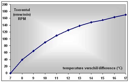
The graph below shows the relation between the temperature difference (x-axis) between the upper and the bottom cylinder plate and the revolution speed (y-axis) of the engine. For this measurements I placed the engine with the bottom plate in a sheet of water with a starting temperature of about 40 ºC. I could measure this temperature exactly and easily during cooling down with a mercury thermometer. The temperature of the upper plate was constant and equal to the ambient temperature.
At higher temperatures as they occur when the engine is placed on a cup with hot water a maximum revolution speed of about 500 revolutions per minute can be reached. The runtime varies from 30 minutes to more than one hour, depending on the size and the isolation properties of this cup. With a small piece of ice in the metal box on the upper plate this runtime can be enlarged significantly, because it reduces the inevitable warming-up of the upper cylinder plate.
The conditions for running on a hand.
So this engine starts moving at about 8°C temperature difference. Indeed some 4° Celsius less that with my former model but I had hoped for some 5° temperature difference to let the engine run under normal ambient circumstances. Because you cannot make the upper plate warmer than 28° Celsius on your hand the ambient temperature must be 28-8=20° Celsius or less which is not or hardly the case in normal living room circumstances. With the aid of a aluminium box with a small ice cube in it on the upper plate the engine will run on your hand. May be a forced remedy but that depends on the way you look at it.
The drawing plan
I made a CAD drawing package for this Low Temperature Stirling; click here for a request.